Difference between revisions of "ADC max1027"
m (Add image) |
m (Add images) |
||
| Line 17: | Line 17: | ||
Then select in Device Drivers->Hardware Monitoring Support->MAX1027 sensor chip (Module) | Then select in Device Drivers->Hardware Monitoring Support->MAX1027 sensor chip (Module) | ||
| + | [[Image:HWMonitor_Linux_Config.png]] | ||
| + | [[Image:MAX1027_Linux_Config.png]] | ||
Once the new config saved, rebuild your image | Once the new config saved, rebuild your image | ||
Revision as of 21:04, 8 May 2007
Instructions to install and use the onboard ADC (MAX1027)
Introduction
The MAX1027 is a 8 channels 10 bits A/D converter with integrated temperature sensor. The SPI1 interface is used to communicate with the device. Moreover, the max1027 is registered as a hardware monitor device. For the moment only a low speed interface (/sys) is available. The eight channels and the temperature are updated every 10ms.
Installation
From the top directory:
# make linux-menuconfig
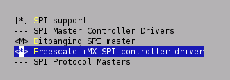
Then select in Device Drivers->SPI support->Freescale iMX SPI controler driver (builtin not module !!)

Then select in Device Drivers->Hardware Monitoring Support->MAX1027 sensor chip (Module)
![]()

Once the new config saved, rebuild your image
# make
On the target, the driver can be started like this
# insmod /lib/modules/drivers/hwmon/hwmon.ko
# insmod /lib/modules/drivers/hwmon/max1027.ko
Usage
Several interfaces in /sys/bus/spi/are created in order to
- read the 8 inputs (inx_input). Result in mV
- read the temperature (temp_input). Result in deg celsius
- modify the default configuration (config and conv)
An input can be read like that
# cat /sys/bus/spi/drivers/max1027/spi1.0/in0_input
The temperature can be read like that
# cat /sys/bus/spi/drivers/max1027/spi1.0/temp1_input
The two configurations files allow direct access to the corresponding register in the MAX1027. For more details, take a look at the datasheet