Difference between revisions of "PS/2"
From ArmadeusWiki
m (Add some precisions for 3,3v keyboard) |
m |
||
| (12 intermediate revisions by 4 users not shown) | |||
| Line 1: | Line 1: | ||
| − | + | =Instructions to connect a PS/2 keyboard to your Armadeus board= | |
| − | + | ==Introduction== | |
Your Armadeus board allows you to connect it a PC keyboard, by using the power of the Spartan3 FPGA (if present on your board). | Your Armadeus board allows you to connect it a PC keyboard, by using the power of the Spartan3 FPGA (if present on your board). | ||
| − | + | ==Hardware connection== | |
| − | |||
[[Image:PS2_Schema.png]] [[http://artemys25.free.fr/armadeus/images/PS2_Schema.png PS2_Schema.png]] | [[Image:PS2_Schema.png]] [[http://artemys25.free.fr/armadeus/images/PS2_Schema.png PS2_Schema.png]] | ||
| − | Connect the PS/2 DATA line to the FPGA pin P137 (IO_L27N_0) and the CLOCK one to the FPGA pin P140 (IO_L01P_0). | + | * Connect the PS/2 DATA line to the FPGA pin P137 (IO_L27N_0) and the CLOCK one to the FPGA pin P140 (IO_L01P_0). |
| − | If your keyboard supports 3,3v power supply you don't need to use the resistor divider brige ! Just use 3,3v from | + | * If your keyboard supports 3,3v power supply you don't need to use the resistor divider brige ! Just use 3,3v from your development board and connect the PS/2 connector pins directly to the FPGA. |
| − | + | ==Firmware installation== | |
| − | Firmware for PS/2 is avaiblable in your SVN repository: | + | * Firmware for PS/2 is avaiblable in your SVN repository: ''firmware/PS2/ps2_top.bit'' |
| − | Copy it to your TFTP directory and follow the procedure | + | * Copy it to your TFTP directory and follow the procedure [[Target_Software_Installation#FPGA_firmware_installation|here]]. |
| − | + | ==Memory Map== | |
The core uses the following register map: | The core uses the following register map: | ||
| − | {|border=1 | + | {| border="1" cellpadding="5" cellspacing="0" summary="Signal connections" |
| − | |- | + | |- style="background:#efefef;" |
| − | + | ! Address !! Name !! Description | |
| + | |- align="center" | ||
|---------------- | |---------------- | ||
|0x12000000 || Status register ||The following bits are used: 0x2 => empty, 0x8=>full, the other bits can be ignored (not used or for debug purposes) | |0x12000000 || Status register ||The following bits are used: 0x2 => empty, 0x8=>full, the other bits can be ignored (not used or for debug purposes) | ||
| Line 36: | Line 36: | ||
|} | |} | ||
| − | === | + | ==Driver== |
| + | Use [[Linux driver for FPGA controlled keyboards| this Linux driver]] to control this IP. | ||
| + | |||
| + | ==BUGS== | ||
| − | Status register | + | Status register starts with value 0x000A -> Fifo Full + Fifo Empty normal ?? |
| − | + | ==Links== | |
* http://www.barcodeman.com/altek/mule/scandoc.php | * http://www.barcodeman.com/altek/mule/scandoc.php | ||
| Line 46: | Line 49: | ||
* http://www.computer-engineering.org/ps2protocol/ | * http://www.computer-engineering.org/ps2protocol/ | ||
| − | [[Category: | + | [[Category:UserInput]] |
Latest revision as of 20:33, 1 August 2010
Contents
Instructions to connect a PS/2 keyboard to your Armadeus board
Introduction
Your Armadeus board allows you to connect it a PC keyboard, by using the power of the Spartan3 FPGA (if present on your board).
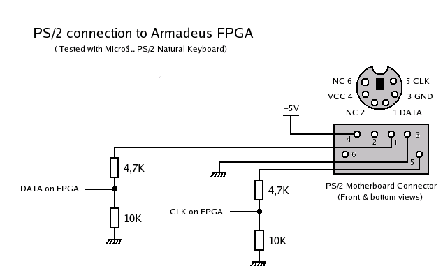
Hardware connection
- Connect the PS/2 DATA line to the FPGA pin P137 (IO_L27N_0) and the CLOCK one to the FPGA pin P140 (IO_L01P_0).
- If your keyboard supports 3,3v power supply you don't need to use the resistor divider brige ! Just use 3,3v from your development board and connect the PS/2 connector pins directly to the FPGA.
Firmware installation
- Firmware for PS/2 is avaiblable in your SVN repository: firmware/PS2/ps2_top.bit
- Copy it to your TFTP directory and follow the procedure here.
Memory Map
The core uses the following register map:
| Address | Name | Description |
|---|---|---|
| 0x12000000 | Status register | The following bits are used: 0x2 => empty, 0x8=>full, the other bits can be ignored (not used or for debug purposes) |
| 0x12000002 | Data read register | The keyboard scancodes can be read from this register. After each access, the next byte from the fifo appears here |
| 0x12000004 | Test register | (has nothing to do with the PS2 interface, just for fun) The lower 8 bit behave like a normal RAM |
| 0x12000006 | Test register | (has nothing to do with the PS2 interface, just for fun) The lower 8 bit behave like a normal RAM |
| 0x12000008 | Test register | (has nothing to do with the PS2 interface, just for fun) The value is always 0x1234, write is ignored |
Driver
Use this Linux driver to control this IP.
BUGS
Status register starts with value 0x000A -> Fifo Full + Fifo Empty normal ??
