Difference between revisions of "FPGA and led"
| (7 intermediate revisions by 3 users not shown) | |||
| Line 1: | Line 1: | ||
| − | This project is intented for people who are new to VHDL. | + | {{Note| This article is only for '''apf9328''' module board}} |
| + | |||
| + | This project is intented for people who are new to VHDL. Code for this design can be found [https://gitlab.com/armadeus/armadeus-bsp on armadeus gitlab] into firmware/leds/button_led/. | ||
We will connect a switch and a led to the FPGA and use some VHDL code to toggle the led state each time the switch is pressed. | We will connect a switch and a led to the FPGA and use some VHDL code to toggle the led state each time the switch is pressed. | ||
| Line 5: | Line 7: | ||
'''Some usefull informations:''' | '''Some usefull informations:''' | ||
| − | The main FPGA page | + | The main FPGA page [http://www.armadeus.com/wiki/index.php?title=FPGA] of the armadeus wiki. |
This document [http://www.cs.uml.edu/~fredm/courses/91.548-spr06/files/qst.pdf] gives a lot of usefull information on how to use ISE Webpack. | This document [http://www.cs.uml.edu/~fredm/courses/91.548-spr06/files/qst.pdf] gives a lot of usefull information on how to use ISE Webpack. | ||
| Line 16: | Line 18: | ||
[[Image:schema.png]] | [[Image:schema.png]] | ||
| − | |||
'''Anatomy of the circuit''' | '''Anatomy of the circuit''' | ||
| Line 22: | Line 23: | ||
The led_top.vhd is a VHDL file where the components of the circuit are instantiated and connected between them. | The led_top.vhd is a VHDL file where the components of the circuit are instantiated and connected between them. | ||
| − | The functional diagram of the circuit is : | + | The functional diagram of the circuit is : |
[[Image:led_top.png]] | [[Image:led_top.png]] | ||
| Line 28: | Line 29: | ||
Benoît Canet / benoit on #armadeus | Benoît Canet / benoit on #armadeus | ||
| + | [[Category: FPGA]] | ||
Latest revision as of 11:41, 30 June 2022
This project is intented for people who are new to VHDL. Code for this design can be found on armadeus gitlab into firmware/leds/button_led/.
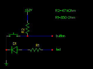
We will connect a switch and a led to the FPGA and use some VHDL code to toggle the led state each time the switch is pressed.
Some usefull informations:
The main FPGA page [1] of the armadeus wiki.
This document [2] gives a lot of usefull information on how to use ISE Webpack.
Page 9 of this document shows the devlight pinout matrix: [3]
Pages 28 and 29 of the APF datasheet shows the mapping of the devlight pinouts with the FPGA pinouts :[4]
Schematic
Anatomy of the circuit
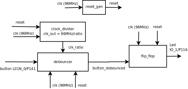
The led_top.vhd is a VHDL file where the components of the circuit are instantiated and connected between them.
The functional diagram of the circuit is :
Benoît Canet / benoit on #armadeus

