Difference between revisions of "CAN bus demo MCP25020"
(New page: This page is related with the DEMOS_MCP25020 package. This software show how to communicate easily on a CAN bus, particularly with the Microchip MCP25020 I/O Expander. This ship is used on...) |
(→Usage) |
||
| (7 intermediate revisions by one other user not shown) | |||
| Line 1: | Line 1: | ||
| − | This page is related with the DEMOS_MCP25020 package. This software show how to communicate easily on a CAN bus, particularly with the Microchip MCP25020 I/O Expander. This | + | This page is related with the DEMOS_MCP25020 package. This software show how to communicate easily on a CAN bus, particularly with the Microchip MCP25020 I/O Expander. This chip is used on the Microchip kit MCP2515DM-PCTL: |
http://fr.farnell.com/microchip/mcp2515dm-pctl/kit-d-eval-mcp2515-controleur-can/dp/1332096 | http://fr.farnell.com/microchip/mcp2515dm-pctl/kit-d-eval-mcp2515-controleur-can/dp/1332096 | ||
| Line 5: | Line 5: | ||
==Driver installation== | ==Driver installation== | ||
| − | + | Please refer to this page (under the '''Driver installation''' section): http://www.armadeus.com/wiki/index.php?title=CAN_bus_Linux_driver#Driver_installation | |
| − | + | ||
| − | + | ||
| − | + | Then, try the instructions in the '''Usage''' and '''Quick test''' sections to check if the CAN network is working correctly. | |
| − | + | ||
| − | + | ||
| − | + | ||
| − | + | ||
| − | + | ||
| − | + | ||
| − | + | ||
| − | + | ||
| − | + | ||
| − | + | ||
| − | + | ||
| − | + | ||
| − | + | ||
| − | + | ||
| − | + | ||
| − | + | ||
==Software installation== | ==Software installation== | ||
| Line 45: | Line 27: | ||
* Reflash rootfs | * Reflash rootfs | ||
| − | == | + | ==Assembly== |
First and foremost, you have to create the bus with the two nodes. | First and foremost, you have to create the bus with the two nodes. | ||
* Add the APF27 as the first node: | * Add the APF27 as the first node: | ||
| Line 71: | Line 53: | ||
[[Image:MCP2515DM-PCTL-J3-localisation.png]] | [[Image:MCP2515DM-PCTL-J3-localisation.png]] | ||
[[Image:MCP2515DM-PCTL-J3-PINOUT.png]] | [[Image:MCP2515DM-PCTL-J3-PINOUT.png]] | ||
| − | {| border="1" cellpadding="5" cellspacing="0" summary=" | + | {| border="1" cellpadding="5" cellspacing="0" summary="J3 Pinout" |
|- style="background:#efefef;" | |- style="background:#efefef;" | ||
! ''' J3 - Pins ''' || ''' Functionnalities ''' | ! ''' J3 - Pins ''' || ''' Functionnalities ''' | ||
| Line 99: | Line 81: | ||
Check that the JP3 is closed on the Microchip demo board, it will add the end line 120ohm resistor of the CAN bus. | Check that the JP3 is closed on the Microchip demo board, it will add the end line 120ohm resistor of the CAN bus. | ||
| − | * Connect CAN L, CAN H and GND | + | * Connect CAN L, CAN H and GND between your APF27-Dev and the MCP2515DM-PCTL |
| + | |||
| + | {| border="1" cellpadding="5" cellspacing="0" summary="J13 Pinout" | ||
| + | |- style="background:#efefef;" | ||
| + | ! ''' APF27-Dev J13 pins ''' || ''' MCP2515DM-PCTL J3 pins ''' || ''' Functionnalities ''' | ||
| + | |---------------- | ||
| + | | 2 || 4 || CAN H | ||
| + | |---------------- | ||
| + | | 3 || 3 || CAN L | ||
| + | |---------------- | ||
| + | | 4 || 2 || GND | ||
| + | |---------------- | ||
| + | |} | ||
==Usage== | ==Usage== | ||
| Line 106: | Line 100: | ||
* Listen on the bus | * Listen on the bus | ||
<pre class="apf"> | <pre class="apf"> | ||
| − | # mcp25020_ctrl listen | + | # mcp25020_ctrl can0 listen |
</pre> | </pre> | ||
| − | * | + | * Blink the D6 Led on the Microchip demo board |
<pre class="apf"> | <pre class="apf"> | ||
| − | # mcp25020_ctrl led- | + | # mcp25020_ctrl can0 led-blink [interval] |
</pre> | </pre> | ||
| − | Interval is 10 to 10000 (The | + | Interval is 10 to 10000 (The blinking interval in ms) |
* Turn ON or OFF the D6 Led on the Microchip demo board | * Turn ON or OFF the D6 Led on the Microchip demo board | ||
<pre class="apf"> | <pre class="apf"> | ||
| − | # mcp25020_ctrl led-state [ON|OFF] | + | # mcp25020_ctrl can0 led-state [ON|OFF] |
</pre> | </pre> | ||
Select ON or OFF to changing the led state. | Select ON or OFF to changing the led state. | ||
* Get the state of the SW2 switch on the Microchip demo board (released or pushed) | * Get the state of the SW2 switch on the Microchip demo board (released or pushed) | ||
<pre class="apf"> | <pre class="apf"> | ||
| − | # mcp25020_ctrl sw2-get | + | # mcp25020_ctrl can0 sw2-get |
</pre> | </pre> | ||
* Get the status of MCP25020 configuration registers | * Get the status of MCP25020 configuration registers | ||
<pre class="apf"> | <pre class="apf"> | ||
| − | # mcp25020_ctrl config | + | # mcp25020_ctrl can0 config |
</pre> | </pre> | ||
See the MCP25020 datasheet for more informations | See the MCP25020 datasheet for more informations | ||
| Line 140: | Line 134: | ||
* http://ww1.microchip.com/downloads/en/DeviceDoc/21664D.pdf (MCP25020 datasheet) | * http://ww1.microchip.com/downloads/en/DeviceDoc/21664D.pdf (MCP25020 datasheet) | ||
* http://www.kvaser.com/can/protocol/index.htm (CAN introduction) | * http://www.kvaser.com/can/protocol/index.htm (CAN introduction) | ||
| + | * http://www.armadeus.com/wiki/index.php?title=User:KevinJ#Communication_with_the_CAN_Bus_of_a_car (Communication with a car CAN bus) | ||
[[Category:Linux drivers]] | [[Category:Linux drivers]] | ||
[[Category:CAN bus]] | [[Category:CAN bus]] | ||
Latest revision as of 13:51, 7 July 2011
This page is related with the DEMOS_MCP25020 package. This software show how to communicate easily on a CAN bus, particularly with the Microchip MCP25020 I/O Expander. This chip is used on the Microchip kit MCP2515DM-PCTL: http://fr.farnell.com/microchip/mcp2515dm-pctl/kit-d-eval-mcp2515-controleur-can/dp/1332096
| |
Warning: Please ensure that you use the trunk version of armadeus (kernel linux-2.6.38.1 is required) before trying the instructions described on this page! |
Contents
Driver installation
Please refer to this page (under the Driver installation section): http://www.armadeus.com/wiki/index.php?title=CAN_bus_Linux_driver#Driver_installation
Then, try the instructions in the Usage and Quick test sections to check if the CAN network is working correctly.
Software installation
$ make menuconfig
    Package Selection for the target  --->
        Armadeus specific tools/utilities  --->
            [*] Armadeus misc demos
            Choose the demos to install  --->
                [*] DEMOS_MCP25020
$ make
- Reflash rootfs
Assembly
First and foremost, you have to create the bus with the two nodes.
- Add the APF27 as the first node:
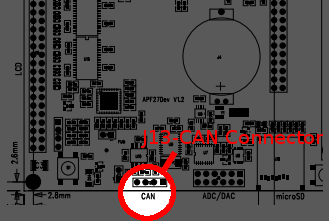
- The pin to connect your APF27-Dev to the CAN bus is on the J13 connector.
| J13 - Pins | Functionnalities |
|---|---|
| 1 | +3V3 |
| 2 | CAN H |
| 3 | CAN L |
| 4 | GND |
Check that the J11 is closed on your APF27-Dev board, it will add the end line 120ohm resistor of the CAN bus.
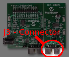
- Add the Microchip kit MCP2515DM-PCTL ( Expander side ) to the CAN bus:
| J3 - Pins | Functionnalities |
|---|---|
| 1 | nc |
| 2 | GND |
| 3 | CAN L |
| 4 | CAN H |
| 5 | GND |
| 6 | nc |
| 7 | nc |
| 8 | +5V |
| 9 | nc |
| 10 | nc |
Check that the JP3 is closed on the Microchip demo board, it will add the end line 120ohm resistor of the CAN bus.
- Connect CAN L, CAN H and GND between your APF27-Dev and the MCP2515DM-PCTL
| APF27-Dev J13 pins | MCP2515DM-PCTL J3 pins | Functionnalities |
|---|---|---|
| 2 | 4 | CAN H |
| 3 | 3 | CAN L |
| 4 | 2 | GND |
Usage
Once your pins are correctly connected, launch your APF27-Dev Board. With the demonstration program, you can:
- Listen on the bus
# mcp25020_ctrl can0 listen
- Blink the D6 Led on the Microchip demo board
# mcp25020_ctrl can0 led-blink [interval]
Interval is 10 to 10000 (The blinking interval in ms)
- Turn ON or OFF the D6 Led on the Microchip demo board
# mcp25020_ctrl can0 led-state [ON|OFF]
Select ON or OFF to changing the led state.
- Get the state of the SW2 switch on the Microchip demo board (released or pushed)
# mcp25020_ctrl can0 sw2-get
- Get the status of MCP25020 configuration registers
# mcp25020_ctrl can0 config
See the MCP25020 datasheet for more informations
Source code
The program source of the demo is viewable in your ARMadeus repository target/demos/mcp25020_ctrl/mcp25020_ctrl.c
Examples program
To create a program with CAN protocol in C/C++, Python, ... is similar to programming a TCP/IP protocol application. Both implement the UNIX socket. You can found some examples in the directory "test" of the socketcan sources, you can found them on:
- http://svn.berlios.de/wsvn/socketcan (trunk->test)
Links
- https://www.ridgerun.com/developer/wiki/index.php/How_to_configure_and_use_CAN_bus (How to configure and use CAN bus)
- http://www.microchip.com/stellent/idcplg?IdcService=SS_GET_PAGE&nodeId=1406&dDocName=en024094 (MCP2515 CAN PICtail Demo Board)
- http://ww1.microchip.com/downloads/en/DeviceDoc/21664D.pdf (MCP25020 datasheet)
- http://www.kvaser.com/can/protocol/index.htm (CAN introduction)
- http://www.armadeus.com/wiki/index.php?title=User:KevinJ#Communication_with_the_CAN_Bus_of_a_car (Communication with a car CAN bus)


