Difference between revisions of "APF27Dev"
From ArmadeusWiki
(Cleanup page) |
m (→Feature list) |
||
| Line 36: | Line 36: | ||
====Video In==== | ====Video In==== | ||
| − | *[[ | + | *[[Camera interface]] |
|| | || | ||
===User Input=== | ===User Input=== | ||
| Line 43: | Line 43: | ||
===Wired communication=== | ===Wired communication=== | ||
| − | * [[Uart]] | + | * [[Uart|UART]] |
* [[SPI]] | * [[SPI]] | ||
* [[I2C]] | * [[I2C]] | ||
| Line 58: | Line 58: | ||
* [[ADC_max1027|ADC (MAX1027)]] | * [[ADC_max1027|ADC (MAX1027)]] | ||
* [[Max5821|DAC (MAX5821)]] | * [[Max5821|DAC (MAX5821)]] | ||
| − | * [[PWM]]: PWM output is on J22 pin 4 (2.8V output, if configured as output) | + | * [[PWM]]: PWM output is on J22 pin 4 <br>(2.8V output, if configured as output) |
* [[GPIO Driver]] | * [[GPIO Driver]] | ||
* [[JTAG]] | * [[JTAG]] | ||
Revision as of 09:44, 12 October 2010
Contents
Description
This is the Armadeus System's standard development board/baseboard for the APF27 module.
The following options are only populated on the "Full" version (APF27DevFull):
Errata
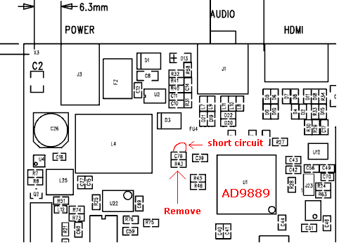
- The APF27Dev DVI/HDMI output may not work correctly: due to a hardware issue on the Powerdown pin of the AD9889, the component may not work as expected (display not detected or going to sleep after some minutes).
- Solution: remove R43 and connect pin PD/A0 (23) to GND. You can place a short circuit over C76.
- Consequence: the AD9889 can no more be placed in low power mode by hardware.
Resources
Feature list
Audio
VideoVideo OutVideo In |
User InputWired communicationStorage |
RealtimeOther
FPGA |
