Difference between revisions of "A simple design with Wishbone bus"
(→Drivers) |
m |
||
| Line 1: | Line 1: | ||
| − | |||
| − | |||
| − | |||
This article intended to explain how to design Wishbone compatible | This article intended to explain how to design Wishbone compatible | ||
Revision as of 19:09, 28 March 2008
This article intended to explain how to design Wishbone compatible components with simple example. The design can be found in sourceforge tree.
Description of wishbone structure for armadeus can be found here in french.
Contents
General structure
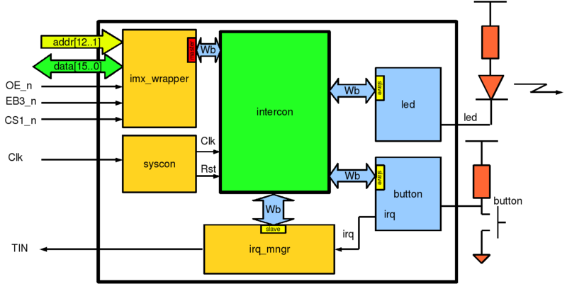
The main functionality of this component is to do the same things that benoît project : switch on a led when a button is pressed.
But to learn about designing Wishbone component and linux driver, the design is little bit more complicated (!).
When button is pressed, the component Wb_button send interrupt signal to irq_mngr. irq_mngr will toggle a flag and send interruption to i.mx processor. A Linux driver on i.mx will read irq_mngr and acknowledge irq by writing '1' on a register. And finally, Linux driver will toggle led value by writing on led register.
imx_wrapper, syscon and irq_mngr are standards
ARMadeus-Wishbone IPs that just been instantiated in our design.
Wb_button and Wb_led are simple slave component we want to integrate in the FPGA.
All these components are connected together with the 'glue logic' component intercon.
Wishbone slave application components
Wb_led
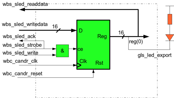
This component is a simple 16-bit Wishbone slave output port, from wishbone specification example (p110).
It is a simple register, that can be read and write. The led is controled with register pin 0.
The VHDL source code is :
library IEEE;
use IEEE.STD_LOGIC_1164.ALL;
use IEEE.numeric_std.all;

-----------------------------------------------------------------------
	Entity Wb_led is
-----------------------------------------------------------------------
    port
    (
		-- Syscon signals
		wbc_candr_reset : in std_logic ;
		wbc_candr_clk	  : in std_logic ;
		-- Wishbone signals
		wbs_sled_writedata : in std_logic_vector( 15 downto 0);
		wbs_sled_readdata  : out std_logic_vector( 15 downto 0);
		wbs_sled_strobe    : in std_logic ;
		wbs_sled_write	  : in std_logic ;
		wbs_sled_ack	      : out std_logic;
		-- out signals
		gls_led_export : out std_logic
    );
end entity;


-----------------------------------------------------------------------
Architecture Wb_led_1 of Wb_led is
-----------------------------------------------------------------------
	signal reg : std_logic_vector( 15 downto 0);
begin

-- connect led
gls_led_export <= reg(0);

-- manage register
reg_bloc : process(wbc_candr_clk,wbc_candr_reset)
begin
	if wbc_candr_reset = '1' then
		reg <= (others => '0');
	elsif rising_edge(wbc_candr_clk) then
		if ((wbs_sled_strobe and wbs_sled_write) = '1' ) then
			reg <= wbs_sled_writedata;
		else
			reg <= reg;
		end if;
	end if;

end process reg_bloc;

wbs_sled_ack <= wbs_sled_strobe;
wbs_sled_readdata <= reg;

end architecture Wb_led_1;
Wb_button
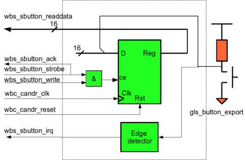
Wb_button component, is like Wb_led but in read only and with an edge detector to rise irq.
The VHDL source code is:
library IEEE;
use IEEE.STD_LOGIC_1164.ALL;
use IEEE.numeric_std.all;

---------------------------------------------------------------------------
Entity Wb_button is
---------------------------------------------------------------------------
	port
	(
		-- global signals
		wbc_candr_reset : in std_logic ;
		wbc_candr_clk 	: in std_logic ;
		-- Wishbone signals
		wbs_sbutton_readdata  : out std_logic_vector( 15 downto 0);
		wbs_sbutton_strobe    : in std_logic ;
		wbs_sbutton_write	  : in std_logic ;
		wbs_sbutton_ack	      : out std_logic;
		-- irq
		wbs_sbutton_irq : out std_logic ;
		-- fpga input
		gls_button_export 		: in std_logic
	);
end entity;


---------------------------------------------------------------------------
Architecture Wb_button_1 of Wb_button is
	---------------------------------------------------------------------------
	signal button_r : std_logic ;
	signal reg : std_logic_vector( 15 downto 0);
begin

	-- connect button
	cbutton : process(wbc_candr_clk,wbc_candr_reset)
	begin
		if wbc_candr_reset = '1' then
			reg <= (others => '0');
		elsif rising_edge(wbc_candr_clk) then
			reg <= "000000000000000"&gls_button_export;
		end if;
	end process cbutton;


	-- rise interruption
	pbutton : process(wbc_candr_clk,wbc_candr_reset)
	begin
		if wbc_candr_reset = '1' then
			wbs_sbutton_irq <= '0';
			button_r <= '0';
		elsif rising_edge(wbc_candr_clk) then
			if button_r /= gls_button_export then
				wbs_sbutton_irq <= '1';
			else
				wbs_sbutton_irq <= '0';
			end if;
			button_r <= gls_button_export;
		end if;
	end process pbutton;

	-- register reading process
	pread : process(wbc_candr_clk,wbc_candr_reset)
	begin
		if(wbc_candr_reset = '1') then
			wbs_sbutton_ack <= '0';
			wbs_sbutton_readdata <= (others => '0');
		elsif(falling_edge(wbc_candr_clk)) then
			wbs_sbutton_ack <= '1';
			if(wbs_sbutton_strobe = '1' and wbs_sbutton_write = '0')then
				wbs_sbutton_readdata <= reg;
			end if;
		end if;
	end process pread;

end architecture Wb_button_1;


