ELDER Project
Project overview
ELDER (Embedded Linux Development for Robotics) Project is a robotic team which participated to the French robotic cup in May 2010. The team used an Armadeus APF27 + APF27Dev boards. This involved to work on both hardware and software designs. One of the goal of this project is to evolve and some parts are still under development.
The main features provided by the APF27 were:
- Robot location computation (X,Y,Orientation), done in hardware by the FPGA
- Robot motion control, done by the FPGA as well
- Multithreading program for high level implementations: path-finding, A.I., gui manager, CAN manager etc.
Project members
This project is actually the work of two students in last year of their Master in Engineering at the University of Strathclyde.
- PaulM
- Sebastien
Links
In order to help the development of this project and the team's communication, a wiki and a subversion repository have been created. Links are bellow.
- Wiki Note that the wiki might be updated during the next days.
- SVN repository
Notes about the Subversion repository
- The actual FPGA firmware files are located at "svn-elder/projects/fpga_fw"
- The actual software files are located at "svn-elder/projects/elder_sw/armadeus"
Students project reports
- PaulM: Motion control, Beacon positioning system, High level software, Motor board: PDF
- Sebastien: Mechanical design, Power Board, Daughter board, GUI: PDF
Detailled informations
Daughter board
Introduction
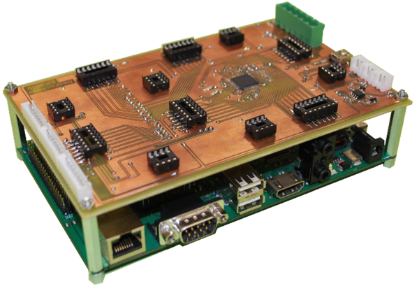
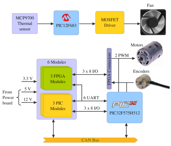
The aim of the daughter board is to interface the APF27 board ( which is used for the intelligence and the motion control) with everything else on the robot such as sensors, actuators, servos, motors, etc... Modules can also be plugged on it according to the robot needs and be interfaced with the Armadeus FPGA or the daughter board’s own microcontroller. Therefore each year, small boards can be developed in line with the project theme and the chosen mechanical solutions.
Requirements
The electrical and mechanical requirements are:
- 100 x 160 mm board : the board has to be the same size as Armadeus board in order to be stacked over it.
- 45 x 45 mm plug-in modules (up to 6 can be plugged) with on each:
- 3.3V logic supply
- 5V and 12V power supply
- CAN Bus
- UART (serial transmission)
- 8 GPIO
- Encoders interface
- Motors interface (PWM and directions)
- Fan control
The daughter board is meant to become a ’mother board’ on which can run the motion control (PID) and the intelligence of the robot.
System design
Microcontroller
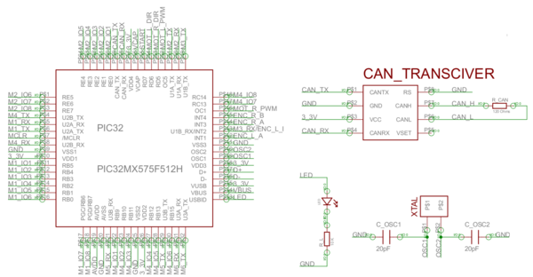
The choice of the microcontroller was based on the requirements, and first an MSP430 from Texas Instrument was chosen. But after two weeks of trying to make a programmer for this type of microcontroller without success, a PIC32MX has finally been selected instead.
The PIC32 is a 32 bits microcontroller architecture family from Microchip, and the PIC32MX575F512H has the following features:
- Max Speed: 80 Mhz
- 10-bits ADC 16 channels
- 5 PWM outputs
- 5 timers
- 53 I/O pins
- 6 UARTS
All this features were enough to fit to the requirements, moreover, this chip could be acquired for free, with the Microchip free samples process.
Note that the microcontroller is also interfaced with the CAN bus, and the implementation is the same as described before for the power board. A LED has been putted on a free pin at the end, which is useful to debug or to make the first ’led blinking test’ for example.
Fan control
The Armadeus board, daughter board, power board and plug-in modules are all mounted in a same box. This configuration generate heat which has to be cooled by a fan in order to have correct performances.
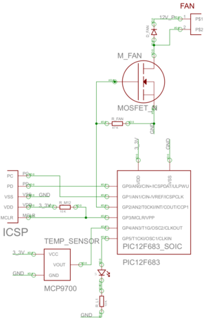
A small dedicated microcontroller is used to realize this function, which again has been chosen from the Microchip manufacturer. It is a PIC12F683 which is small (8 pins), has got an ADC for the temperature reading and a PWM output for the fan speed setting.
The fan is driven by a MOSFET which is triggered by the PWM, and gives the possibility to apply a 12V supply voltage directly on it.
A freewheeling diode is also putted between the fan’s terminals, in order to protect it from being damaged by instant high voltages generated by the inductive property of the motor.
Encoders interface
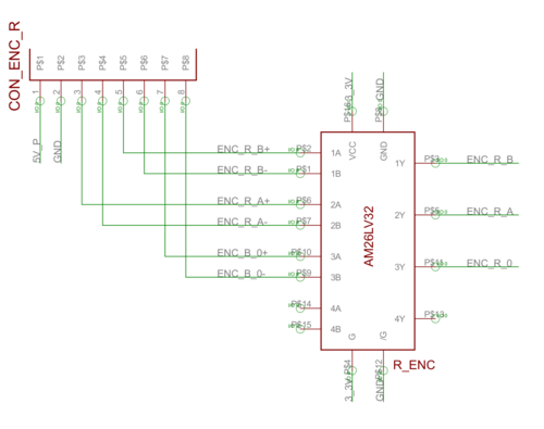
The encoders are used to measure accurately the distance traveled by the robot, it gives 1024 ’ticks’ for each wheel revolution. These ticks are transmitted via two channels A and B, which both are differential outputs of the encoder.
In order to treat these signals, AM26LV32 differential line receiver are used. This kind of chip can be supplied with only 3.3V however it accepts 5V inputs, which is the minimum supply level for the encoders.
As a result, it plays a double role as converting the differential input in a single output, and as converting a 5V input to a 3.3V output which is acceptable for the FPGA or the microcontroller.
Modules sockets
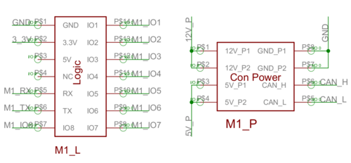
Each module can access to a 5V and 12V power supply generated from the power board, and a 3.3V logic supply generated by the daughter board. It also has the possibility to use the CAN bus or an UART from the PIC32MX.
Three of six modules have 8 GPIO each directly mapped to the Armadeus board’s FPGA, and the 3 others have these available GPIO linked to the PIC32MX microcontroller’s ports.
Program
PIC32MX
At this stage of the project, there is no module which has been realized, so the only program running on the PIC32MX is blinking led code. This one has been developed in order to test if microcontroller was working, according to the configuration bits. This test has been successful, now need to be debugged the UART and the CAN bus.
PIC12F
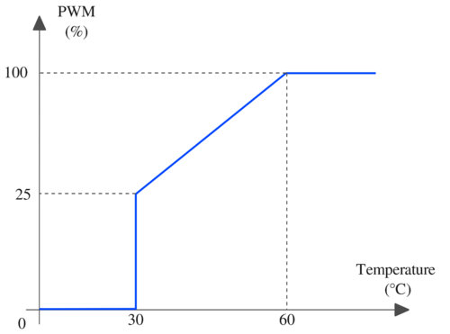
For the PIC12F which control the fan, the program is very simple, there is a main loop in which the ADC is read, and this value determines the PWM duty cycle. The relation between the temperature and the duty cycle value is shown in the figure below , where three phases can be seen:
- before 30°C, the fan is stopped.
- between 30°C and 60°C the speed of the fan is linearly increasing according the temperature. An initial offset is required to start the fan’s motor.
- after 60°C, the fan remains at 100% speed
There is also a blinking LED, to be sure the microcontroller is correctly running.
Onboard GUI
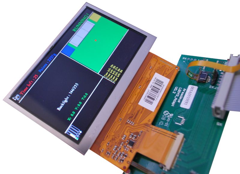
The APF27 board can be interfaced with graphical LCD display and its associated touch screen.
During the matches, the robot has to be completely autonomous, without a computer plugged to it.
A simple graphical user interface has been developed in order to be able to display any type of useful information on the robot such as:
- The battery level
- The time left during the matches
- The position of the robot on the game table
- The number of points the robot has scored
On this screen, there is also a console to display miscellaneous messages.
The touch screen allows the user to be interactive with the robot, to browse menu and ask the robot execute an action. This can be useful just before the matches to check if everything works properly.
The LCD is directly interfaced with the SDL library. This library can be used in C language to develop multimedia application on various platforms.
More information comming soon


