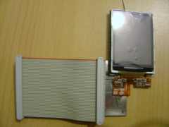
MotLCD
How to connect the Moto A910 LCD to the APM dev Board. This LCD will probably be part of other Moto phones.
Adapter schematics
The schematics of the LCD adapter board have been placed under SVN and can be found here: svn://ericjarrige.homelinux.org/armadeus/trunk/hardware/LCD_ADAPT_MOT/schema.pdf
Connections
Just connect signals with same names together, excepted for the following ones:
| LCD Adapt board | APM dev board |
| TB_RL | GND |
| CM | GND |
| MCLK | LSCLK |
| OE | OE_ACD |
| HSYNC | LP_HSYNC |
| VSYNC | FLM_VSYNC |
| SD | CONTRAST with 1k pullup to 3.3V |
| And due to an error on first print of the adapter board, connect: | |
| B4 | B4 |
| B3 | B0 |
| B2 | B1 |
| B1 | B2 |
| B0 | B3 |
As the fine pitch connector of the LCD is symetrical, take care when connecting the LCD to the Adapt board !!.
The LCD must be placed over the DC/DC converter (not mounted):

(!! don't forget to isolate the back of the LCD, with some rubber for ex. !!)
The Berg connector is reference to P2 and the dine pitch is P1 in the schematics.
The DC/DC converter is not yet tested so you will need a ~12V supply for the LCD backlight.... this is why you have a separate cable on the LCD adapt. This 12V supply can be the same as the one used for the APM dev board.